New solar panels and a PV Grid Tie inverter charging 4 Li-ion batteries - Why is my meter still clocking similar usage? Have my batteries been installed correctly?
New solar panels and a PV Grid Tie inverter charging 4 Li-ion batteries - Why is my meter still clocking similar usage? Have my batteries been installed correctly?
Installation has just (Friday 13/11/20) been completed on my roof in Stockport of 28 solar panels and a PV Grid Tie single phase inverter charging 4 x 3.5kWh Li-ion batteries via a 3kW AC Coupled inverter. The included phone app shows that I am now drawing very little grid power and the batteries are fully charging even on fairly dull days, and are still fairly “full’ next morning. However, my daily meter readings are little changed from pre-solar times which means that my electricity bills will not decrease. I am not particularly concerned with selling power back to the grid as I understand that this is poorly rewarded at this time, but I am worried that the electricity which the sun is now freely providing directly for my consumption will still be charged for as if it were coming from the grid. I was expecting my meter to more or less stand still, or even “run backwards” but that isn’t happening. Is there a way to fix this please?
It’s worth mentioning that if you are concerned about the wiring of your solar panels to your smart meter we’d recommend contacting your solar panel installer who are responsible for ensuring the connection between your panels and the meter are correct.
I spent some time today meeting a professional battery installer and qualified electrician. We had a moment to look at the photos which @dnshorto has provided and I gleaned some useful information.
So what follows is with grateful thanks to Marcus of GMEC ELECTRICAL in Barnstaple:
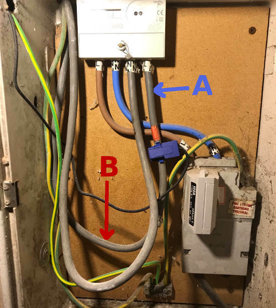
1: He commented that the current clamps can be affected by the electro-magnetic field from adjacent cables. Your installer decided to move the clamp higher on the live-tail to Position A in this photo:
However, this is still in close proximity to the Neutral-Tail, immediately to the left.
Marcus says he tries to find a location where the distance between the two conductors is greater. I’ve marked B as a possible position.
This would enable the Live-Tail to be reinstalled with the outer plastic casing intact.
2: Marcus has previously installed the same Pylontech US3000 Storage Batteries as you have.
However he has never considered attempting to place them in the orientation shown in your photo above, nor so close together.
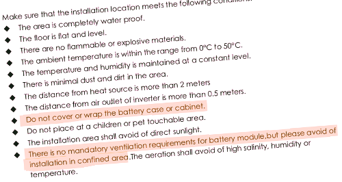
I have therefore downloaded the Pylontech Installation Manual from here, and checked to see what it advises. Read the two points which I’ve highlighted:
As originally supplied, these US3000 Batteries have mounting brackets to be fitted horizontally within a 19-inch rack. The positioning of the M6 bolt holes ensures that they are held apart by about 30mm.
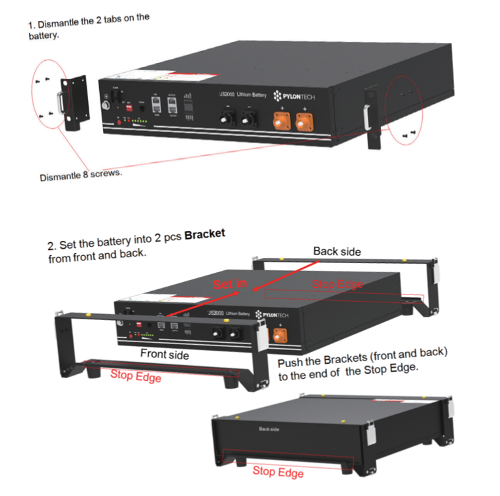
If they are to be stacked without a 19-inch rack cabinet, then there are feet/brackets which should be fitted in place of the M6 bolt brackets:
Installation Manual, page-17
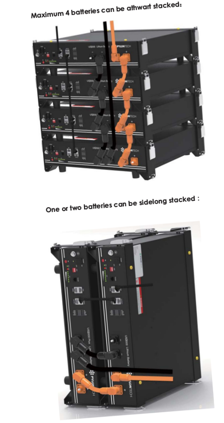
These feet/brackets allow up to four batteries to be stacked horizontally, but only two vertically:
Installation Manual, page-19
The reason for these spacers becomes obvious when you read the fault-finding guide at the back of the Manual. It states that the batteries will cease to charge/discharge if the enclosure temperature rises above 50°C.
Given that you have 28 PV panels producing a possible 9.5kW of power, it doesn’t take much to see that this is capable of rapidly charging just 14kWh of storage. And it’s that high current which will cause the temperature to rise.
It’s possible that your Installer has allowed for this and compensated by reducing the maximum charge current being sent from the Growatt Inverter. But that seems to defeat the object of having had so many panels installed in the first place.
Let me finish this particular post by pointing out that it is still early days for installation of domestic battery storage, but there are already in excess of 100 models available in the UK. It simply isn’t possible for every supplier to know how to specify and install all possible combinations.
Everyone is still on a very steep learning curve, and I don’t think that your Supplier should be blamed for failing to get this site optimal. The arrangement is still inherently safe, and will simply shut-down the batteries if the charge current is too high.
It’s much more important that we can share these sorts of details with Installers in the expectation that the pooling of such knowledge will help to ensure better optimised installations in the future.
So what I’ve just written above isn’t enough to warrant an irate complaint!
@Transparent thanks again for your comments and questions which I will try to answer.
The clamp on the meter tail has a rather anonymous black wire which I have been unable to positively trace. A similar-looking black wire does indeed enter the cable gland below the Growatt marked “Six Holes” but I cannot be sure this is it.
The 6 cables connected to the base of the Solis inverter are indeed the 6 coming directly from the roof array. (as you enquire in question 4). There is no evidence of any lightning protection or ani-surge protection, so I intend to ask the system provider about this lack. In your opinion, are these just desirable or definitely necessary? Regarding your supplementary question about the hole in the garage wall, I drilled this myself with a core drill and attempted a fall to the outside, which the camera angle doesn’t show. It ended up not far off level, but at least it doesn’t slope down to the inside!
The 2 larger consumer units in the earlier photo are existing Distribution Boards 1 and 2. The smaller white unit in this photo above DB1 is a new circuit-breaker which the electrician called a ‘garage unit’. I recall seeing another blue cable clamp sensor within this box also. The top item is part of a security system.
From the battery earth posts another anonymous black cable (which I suspect should be green & yellow) goes, as far as I can see, to the ‘garage unit” which has a green yellow cable to the meter cupboard earth. This can be seen in the final picture below, coming through a regrettably clumsy hole in the glass-fibre meter box. This earlier photo also shows the blue cable clamp in its original ineffective position.
I will be keeping an eye on how the 4 Pylontech batteries perform on a day-to-day basis. Sunny days make a big difference, so November to March they may not get a full charge each day. For instance, by late evening yesterday they had dropped too low to provide domestic power so we began drawing from the grid, but that was an extra dull, gloomy day here in the North West. Given an hour or two of sun each day I predict they will provide most of our night-time needs.
It’s worth mentioning that if you are concerned about the wiring of your solar panels to your smart meter we’d recommend contacting your solar panel installer who are responsible for ensuring the connection between your panels and the meter are correct.
I spent some time today meeting a professional battery installer and qualified electrician. We had a moment to look at the photos which @dnshorto has provided and I gleaned some useful information.
So what follows is with grateful thanks to Marcus of GMEC ELECTRICAL in Barnstaple:
1: He commented that the current clamps can be affected by the electro-magnetic field from adjacent cables. Your installer decided to move the clamp higher on the live-tail to Position A in this photo:
However, this is still in close proximity to the Neutral-Tail, immediately to the left.
Marcus says he tries to find a location where the distance between the two conductors is greater. I’ve marked B as a possible position.
This would enable the Live-Tail to be reinstalled with the outer plastic casing intact.
2: Marcus has previously installed the same Pylontech US3000 Storage Batteries as you have.
However he has never considered attempting to place them in the orientation shown in your photo above, nor so close together.
I have therefore downloaded the Pylontech Installation Manual from here, and checked to see what it advises. Read the two points which I’ve highlighted:
As originally supplied, these US3000 Batteries have mounting brackets to be fitted horizontally within a 19-inch rack. The positioning of the M6 bolt holes ensures that they are held apart by about 30mm.
If they are to be stacked without a 19-inch rack cabinet, then there are feet/brackets which should be fitted in place of the M6 bolt brackets:
Installation Manual, page-17
These feet/brackets allow up to four batteries to be stacked horizontally, but only two vertically:
Installation Manual, page-19
The reason for these spacers becomes obvious when you read the fault-finding guide at the back of the Manual. It states that the batteries will cease to charge/discharge if the enclosure temperature rises above 50°C.
Given that you have 28 PV panels producing a possible 9.5kW of power, it doesn’t take much to see that this is capable of rapidly charging just 14kWh of storage. And it’s that high current which will cause the temperature to rise.
It’s possible that your Installer has allowed for this and compensated by reducing the maximum charge current being sent from the Growatt Inverter. But that seems to defeat the object of having had so many panels installed in the first place.
Let me finish this particular post by pointing out that it is still early days for installation of domestic battery storage, but there are already in excess of 100 models available in the UK. It simply isn’t possible for every supplier to know how to specify and install all possible combinations.
Everyone is still on a very steep learning curve, and I don’t think that your Supplier should be blamed for failing to get this site optimal. The arrangement is still inherently safe, and will simply shut-down the batteries if the charge current is too high.
It’s much more important that we can share these sorts of details with Installers in the expectation that the pooling of such knowledge will help to ensure better optimised installations in the future.
So what I’ve just written above isn’t enough to warrant an irate complaint!
I will try moving the clamp to the position suggested.
The battery proximity issue is not likely to cause problems before next summer, but I can well see that a hot and sunny day might easily generate excess heat the way the batteries are stacked now. There is in fact lateral space on the shelf to form a void approximately 100mm wide between batteries 2 and 3, thus moving a little closer to the manufacturer’s recommendation. Scope too for heat-controlled forced air fan ventilation if needed.
Note: When moving a current-clamp, make sure that you keep it the “right way around”.
The control software gets in a real tizzy if the current clamp reverses the concept of import and export, and most likely leaves you with a large bill as a consequence!
That’s the posts about lightning protection for Solar Panels, which @Tim_OVO ‘s referring to.
I raised the issue here because I checked the specification for the Solis Inverter which @dnshorto has just had installed. It stated that the unit has integral “surge protection”, but without saying what it was protecting against.
As the Inverter does not appear to have a separate earth connection through which it could send the energy from a lightning strike, I’m assuming that the anti-surge provision is to prevent spikes/transients rather than a lightning discharge.