New solar panels and a PV Grid Tie inverter charging 4 Li-ion batteries - Why is my meter still clocking similar usage? Have my batteries been installed correctly?
New solar panels and a PV Grid Tie inverter charging 4 Li-ion batteries - Why is my meter still clocking similar usage? Have my batteries been installed correctly?
Installation has just (Friday 13/11/20) been completed on my roof in Stockport of 28 solar panels and a PV Grid Tie single phase inverter charging 4 x 3.5kWh Li-ion batteries via a 3kW AC Coupled inverter. The included phone app shows that I am now drawing very little grid power and the batteries are fully charging even on fairly dull days, and are still fairly “full’ next morning. However, my daily meter readings are little changed from pre-solar times which means that my electricity bills will not decrease. I am not particularly concerned with selling power back to the grid as I understand that this is poorly rewarded at this time, but I am worried that the electricity which the sun is now freely providing directly for my consumption will still be charged for as if it were coming from the grid. I was expecting my meter to more or less stand still, or even “run backwards” but that isn’t happening. Is there a way to fix this please?
It’s worth mentioning that if you are concerned about the wiring of your solar panels to your smart meter we’d recommend contacting your solar panel installer who are responsible for ensuring the connection between your panels and the meter are correct.
I spent some time today meeting a professional battery installer and qualified electrician. We had a moment to look at the photos which @dnshorto has provided and I gleaned some useful information.
So what follows is with grateful thanks to Marcus of GMEC ELECTRICAL in Barnstaple:
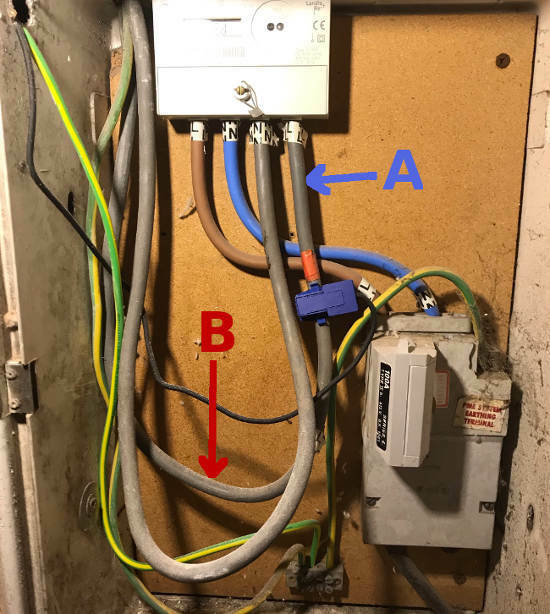
1: He commented that the current clamps can be affected by the electro-magnetic field from adjacent cables. Your installer decided to move the clamp higher on the live-tail to Position A in this photo:
However, this is still in close proximity to the Neutral-Tail, immediately to the left.
Marcus says he tries to find a location where the distance between the two conductors is greater. I’ve marked B as a possible position.
This would enable the Live-Tail to be reinstalled with the outer plastic casing intact.
2: Marcus has previously installed the same Pylontech US3000 Storage Batteries as you have.
However he has never considered attempting to place them in the orientation shown in your photo above, nor so close together.
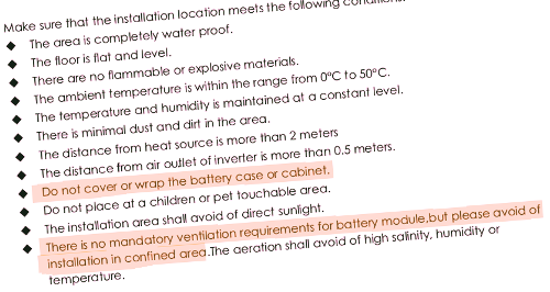
I have therefore downloaded the Pylontech Installation Manual from here, and checked to see what it advises. Read the two points which I’ve highlighted:
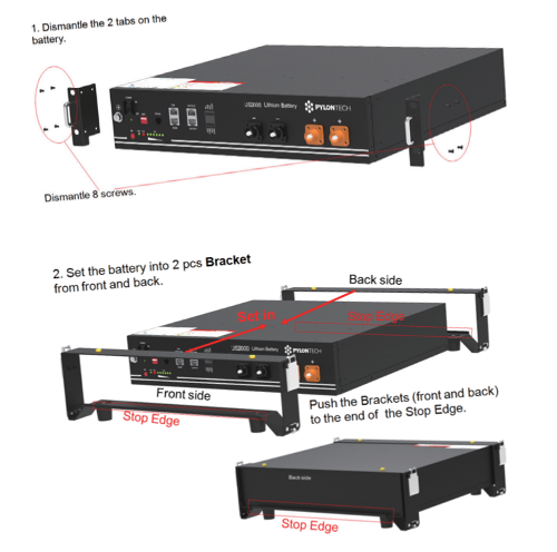
As originally supplied, these US3000 Batteries have mounting brackets to be fitted horizontally within a 19-inch rack. The positioning of the M6 bolt holes ensures that they are held apart by about 30mm.
If they are to be stacked without a 19-inch rack cabinet, then there are feet/brackets which should be fitted in place of the M6 bolt brackets:
Installation Manual, page-17
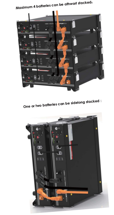
These feet/brackets allow up to four batteries to be stacked horizontally, but only two vertically:
Installation Manual, page-19
The reason for these spacers becomes obvious when you read the fault-finding guide at the back of the Manual. It states that the batteries will cease to charge/discharge if the enclosure temperature rises above 50°C.
Given that you have 28 PV panels producing a possible 9.5kW of power, it doesn’t take much to see that this is capable of rapidly charging just 14kWh of storage. And it’s that high current which will cause the temperature to rise.
It’s possible that your Installer has allowed for this and compensated by reducing the maximum charge current being sent from the Growatt Inverter. But that seems to defeat the object of having had so many panels installed in the first place.
Let me finish this particular post by pointing out that it is still early days for installation of domestic battery storage, but there are already in excess of 100 models available in the UK. It simply isn’t possible for every supplier to know how to specify and install all possible combinations.
Everyone is still on a very steep learning curve, and I don’t think that your Supplier should be blamed for failing to get this site optimal. The arrangement is still inherently safe, and will simply shut-down the batteries if the charge current is too high.
It’s much more important that we can share these sorts of details with Installers in the expectation that the pooling of such knowledge will help to ensure better optimised installations in the future.
So what I’ve just written above isn’t enough to warrant an irate complaint!
A glimmer of hope, and a translation! The installers returned and modified the wiring. The clamp on the meter cable that senses which direction the current is flowing has been moved. The double insulated cable has had one sheath pared back and the clamp positioned over the singly-insulated section. When the meter is stopped (by the solar power or battery taking over) a red light shines. The mysterious legend rEd simply means what it says: RED! Since the modification, the red light has been on and for the past hour the meter has not moved. Will report tomorrow when I read the meter again at 3pm if this has solved my problem .
For the sake of others who will come across this Topic in future, let me explain that a “current clamp” measures the Amps flowing in the wire that it grips using electromagnetism, and without the need to actually connect to the conductor.
I’m pleased to see that the installer has been and rechecked the clamp. I’m less happy that it has been necessary to remove the outer layer of insulation from the live-feed to your Consumer Unit
If this is a temporary situation whilst they try to source a better current-clamp, then that’s fine. But there are really good reasons why the meter tails must be double-insulated! Let me just tag @PeterR1947 and see if he’d like to comment further.
As for your house having been granted G99 certification, that’s excellent. Your Solar Installer has done well for you!
You are unlikely to ever achieve the 9.66kW theoretical output from your solar panels because their efficiency drops slightly when they get hot. Depending on the manufacturer and the chemistry of the silicon technology, you are probably going to get between 90-95% of that rating in full/bright sunlight in summer.
Although we do have full sunshine during some cold days in winter, when the heating effect is reduced, the sun is lower in the sky, and thus it’s rays won’t be at right-angles to the panels.
Even so, the way in which your electrical control systems have been configured is equally important. It’s likely that the DNO has been satisfied that you won’t be exporting from all 28 panels and the 4 storage batteries simultaneously! There must be a fail-safe interlock within the software to prevent that.
The outer sheath is actually for protection of the cable insulation rather than an extra layer of insulation. It should not be cut back as shown in the picture, the danger is that the inner insulation has been cut in the process causing a potential shock hazard.
The outer shield should only be trimmed back a couple or so mm past the inner insulation so when the tail is connected, the outer shield then fills the the terminal sleeve and prevents any access
My ‘dumb” digital meter which was in the house when we moved in 6 years ago alternates every few seconds between the current kWh reading and the uninformative legend: “rEd”. Does that convey a meaning to anyone?
The legend rEd stands for reverse Electricity detected; it was originally in the meter firmware to detect meter tampering. Obviously, when solar panels are generating more than is required, electricity is flowing backwords through the meter, hence the rEd message. It doesn’t indicate a fault and can be safely ignored,
As promised yesterday, here’s the diagrams of the two main methods by which solar panels are connected to the Distribution Grid.
Firstly, the most common method, whereby the DC output from the solar string is sent straight to an Inverter, which changes it to 230v AC 50Hz.
Note that the Storage Battery is also AC-connected. This arrangement is favoured by those whose houses already have a solar-inverter on a PV Array which was installed several years previously.
The alternative configuration is to choose a Storage Battery which has DC input from the solar panels. There is no separate Inverter because the necessary conversion to 230v AC is made within the Battery Unit.
I’ve kept labeling to a minimum, and deliberately omitted any annotations related to maximum permitted parameters and sizes of panels or battery. Please ask if you’d like to have these details.
This Forum is amazingly helpful and useful, clearly because of the well-informed and intelligent contributors! Thank you @PeterR1947 for pointing out the issues with reducing the cable insulation on the meter tails, and for translating rEd. Not “Red” at all, something the professional installers didn’t know. Thank you @Transparent for the alternative wiring diagrams to show the two main methods of doing a grid-connection with PV Panels and Home Battery Storage, and for all your other shared wisdom. My own system uses two inverters, a Solis to convert the incoming solar DC to 230V AC, and a Growatt to charge the battery bank. Apparently the solar array was too large to use a hybrid inverter to perform both functions. Photos below.
On any reasonably sunny day, even a dull day with occasional sunshine all 4 batteries are showing a full charge which isn’t bad for November!
But the brilliant news is that my meter has finally been brought under control! Instead of the daily 9 to 10 kWh I have been seeing since 28th October the last 24 hours has registered 1 kWh. The Reverse Electricity Detected lamp has been on more or less continuously. All this searching for an answer has come down to the failure of the detection clamp to penetrate the double insulation of the meter tail. Nothing wrong with the set up after all, apart from this tiny fault. It’s just annoying that 20 days of say 9 units = 180 units at say 13p = £23 will have to be paid for electricity which the sun has been providing free of charge! I am very grateful to OVO for hosting this very helpful Forum which has facilitated the solution to my problem. Thank you.
@dnshorto@Transparent the detection clamp on the meter tail is purely there to measure current flowing, I’m surprised it wouldn’t work through a double layer. As regards the consumption, are you reading that from a device attached to the solar/battery controller? If you are, that is fine, it shouldn’t have made any difference to the electricity you were exporting so I think it’s unlikely you have had to pay for that 180 units. If you were taking readings from the electricity meter itself then I’m puzzled.
Many thanks for the photos @dnshorto This helps us to pursue some of the loose ends with your particular arrangement.
1: Picking up what @PeterR1947 has just said, I can think of several reasons why a current clamp has been placed on the live meter “tail”. To help narrow this down, can you tell us what it connects back to? Is it the Growatt inverter?
2: Your first photo appears to show two bundles of 4mm² Solar Cable entering the house (garage?) via a hole now stopped up with white mastic. Are those the same six cables we can see entering the bottom left corner of the Solis inverter in the second photo?
And, incidentally, when I drill cable entry holes like this, I normally make it slope downhill to the outside so that any condensation runs out. I also line the hole with conduit and don’t allow anything to grip the cable. This permits heat to escape and for thermal-expansion in hot weather.
It may just be the angle of the camera, but it looks to me like your hole slopes the other way. If so, then you’re relying on the mastic to keep out rain, whilst any (thermal) movement of those cables will be pulling against it.
This point is a bit “picky” but, as I’m a self-builder, it’s the sort of detail which matters to me because I’m going to be living with the consequences of that hole for years to come!
3: To the right of the Growatt there are four enclosures on the wall. The bottom two appear to be both consumer units. What are the others, and are they part of the solar-install which has just been completed?
4: Earthing. I can see some hefty earth-wire connecting the four battery packs, which I assume then runs to the house’ central earth point (in a consumer unit?).
I would also expect to see some anti-surge units at the first point where the roof-top cables connect to an internal device. Is this device the Solis, or do the cables first go to a box which contains lightning protection, and possibly some isolating switches and fuses?
Heads up I have dutifully moved this over to it’s own topic!
I can also help to make sure we have one all encompassing ‘best answer’ assigned to this. That way it will help anyone else with a similar issue. Hopefully the next decade will see lots of similar set ups as @dnshorto so this might be invaluable advice!
We’re nearly there I feel….
Carbon neutral - we need a community to get there! My green tech: Aclara SGM 1411-B smart meter, Chameleon IHD6
@PeterR1947 the readings were being taken daily from the original house meter. It is obviously from these readings that my electricity bill will be calculated, which is why I was concerned. The readings on the new solar-linked meters and phone app were all very positive (very low grid consumption), but those would be irrelevant to my power supplier. Thankfully, the re-positioning of the clamp closer to the conductor by removing a layer of insulation has stopped the meter when the solar or battery is supplying the power. From your helpful comments on the need for double insulation of the meter tail, and indication that a more sensitive clamp could be the answer, I intend that the present fix is only temporary.