Blog

A guide to preventing an EVSE (Electric Vehicle Supply Equipment) from discharging a home battery

  • August 11, 2025
  • 5 replies
  • 145 views
A guide to preventing an EVSE (Electric Vehicle Supply Equipment) from discharging a home battery
Peter E
Plan Zero Hero
Forum|alt.badge.img+1

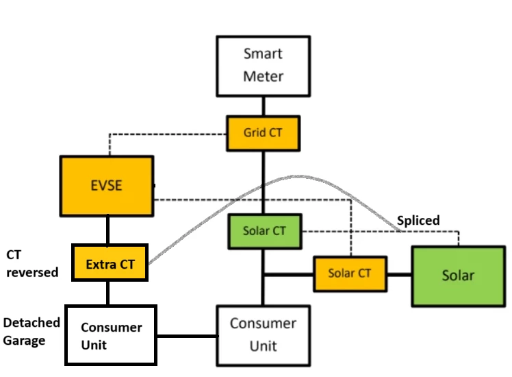
CONNECT THE EVSE UPSTREAM OF THE SOLAR/BATTERY CT CLAMP – That’s it!


This way the Solar/Battery doesn’t see the power taken by the EVSE unit. Quite often the EVSE is
wired downstream of the Solar/Batter CT clamp from the Consumer Unit so it sees (monitors) the
load from the EVSE, should an EVSE slot be programmed into the period when the battery is set to
discharge into the house load. The example is shown for the Zappi EVSE. Other units may not have
the Solar CT Clamp input/option.


Note: EVSE/Solar CT Clamp (orange) may or may not be available on some types of EV but all EVSEs
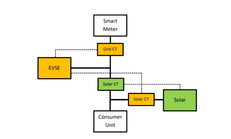
have the Grid CT Clamp.


Downsides


  • Export to the grid may now be limited


  • The solar/battery system is no longer collecting all your energy usage stats as it can’t see any
    load from the EVSE. However, if the EVSE has a Solar/Battery CT Clamp it should be able to
    monitor the Solar/Battery energy flow as well.


Other considerations


  • Individual EVSEs have different options in their sub-menus to manage battery discharge
    without rewiring/moving clamps. As an example the Zappi has a menu to manage battery
    discharge because it has a CT Clamp that goes on the power line to the Solar/Battery unit.


  • Home Assistant is another way of managing the power flows within the system but needs a
    level of technical competence to fit and to set up the sometimes complex options available.


  • There is always the possibility that you want the set the system up in a way that is unique in
    which case that will be a case of researching possible answers.


Related Links


Zappi (myenergi)

https://support.myenergi.com/hc/en-gb/articles/4716922623633-Hybrid-PV-Battery-Set-up-Avoid-
Draining


Hypervolt

https://support.hypervolt.co.uk/en/knowledge-base/how-to-adjust-your-ess-setup-to-prevent-
battery-drain


Andersen
https://andersen-ev.com/


No specific advice seems to be available in terms of setting up the EVSE to prevent this but wiring


Indra
https://www.indra.co.uk/support/smart-charging-and-solar/


Very little information available on Solar CT Clamps although the documentation does mention a
Solar mode. The link is next to useless for information.


Searching for information also throws up a lot of videos of various quality so a sample of those might
prove to be useful.

5 replies

Ben_OVO
Community Manager
  • Community Manager
  • August 11, 2025

@Peter E thanks again for writing up this article - we really appreciate your help, and this outlines the solution really clearly 😁.


Peter E
Plan Zero Hero
Forum|alt.badge.img+1
  • Author
  • Plan Zero Hero
  • August 11, 2025

Thank you ​@Emmanuelle_OVO and ​@Ben_OVO for turning my diagrams and words in something presentable. I hope that this helps to resolve at least some of the issues encountered.


Peter


Forum|alt.badge.img+2
  • Carbon Catcher*
  • August 11, 2025

Useful thread, especially as this issue comes up regularly. 

In my case I couldn’t use any of these methods easily without significant additional costs. 

My EVSE, solar PV, inverter and home battery are all in a detached garage over an underground 30m SWA cable. I didn’t want the hassle of EVSE or inverter programming schedules to avoid battery-to-battery drain, but wanted to retain the full 24/7 flexibility.

Here is an alternative solution. It works well and could even be used in standard solutions where you might not want to move the EVSE upstream. 

The extra CT Clamp is attached on the EVSE supply but in a reverse direction, and then spliced into the main solar CT Clamp. When the EV takes a charge, that charge is effectively subtracted from the main load that the inverter monitors, and hence the home battery wont drain off as it doesn’t see the EVSE load.

No EVSE AC rewiring required, just a new CT and its cabling. Still allows excess solar to charge EV if required.

(note: in my solution the solar PV is actually on the left hand CU, not as the diagram represents).


Peter E
Plan Zero Hero
Forum|alt.badge.img+1
  • Author
  • Plan Zero Hero
  • August 12, 2025

@oho Thank you very much for your useful feedback. In common with a lot of people you’ve had to find a unique solution to charging your car with the layout of the house, garden, drive, garage etc and consequently the ‘standard’ solution for avoiding this issue can’t be used without cost. It’s brilliant that you have found your own solution and you marked up the diagram for others to have a look at. Of equal importance is that you have demonstrated that you can be innovative with possible solutions to come up with the fix that suits your circumstances. I take my hat off to you!


Peter


Forum|alt.badge.img+2
  • Carbon Catcher*
  • August 12, 2025

Thanks ​@Peter E 

I did indeed have to find an unique solution, but this one would actually work easily for anyone with the battery-to-battery drain issue. Even with a typical installation.

It was roughly 30 minutes work for a competent person. And avoids having to move the EVSE upstream post install, which is a more complex change.