
I hereby start a new thread, with a link to Open Energy Monitor.
I blame the interest shown by

I hereby start a new thread, with a link to Open Energy Monitor.
I blame the interest shown by
Your progress is faster than mine
I’m building my Pi & eMonPi Shield boards into a configuration which includes an ‘always on’ 5v UPS. Firstly the instructions state that a power-loss during operation can destroy the SD-card(!)

… but I’d also like to monitor what interesting anomalies occur when power fails and is then restored.
Here’s a photo of my well-pump meter taken on 4th March ‘21 when power was being restored from a damaged 11kV supply:
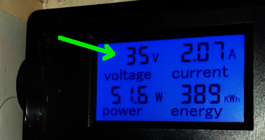
A mains supply hovering outside the permitted 216-253v can do all sorts of damage to equipment. In this case the fault remained for around 3 or 4 minutes whilst I took several photographs.
Your progress is faster than mine
...
A mains supply hovering outside the permitted 216-253v can do all sorts of damage to equipment. In this case the fault remained for around 3 or 4 minutes whilst I took several photographs.
I’m only playing with numbers at the moment (which is easy for me) as a displacement activity from trying to understand what my new oscilloscope can tell me about optical pulse mis-counting (which is all quite far out of my comfort zone).
Of increasing urgency is the setting up a bit of temperature monitoring on various pipes - I would like to see how inefficient our old boiler is, by comparison with its replacement, before it’s ripped out a week tomorrow. Arguably this should be easy for a retired metrologist used to analysing temperature data sensed with microK precision (and at room temperatures, not cryogenic) but I was the theorist and had experimental colleagues to build the equipment and make it work ...
In a previous decade, other colleagues spent a LONG time fretting over the imminent reduction in mains voltage from 240 to 235 (their work depended on a 50 year old Van de Graaff generator that needed all the help it could get). In the end of course, mains voltage didn’t really change, only the allowed tolerance. But they wisely found a way not to rely on the ancient machine.
For the moment, I’ll just keep my fingers crossed re the risk of surges damaging my shiny new Emonpi things.
We seem to have very complementary skills ![]()
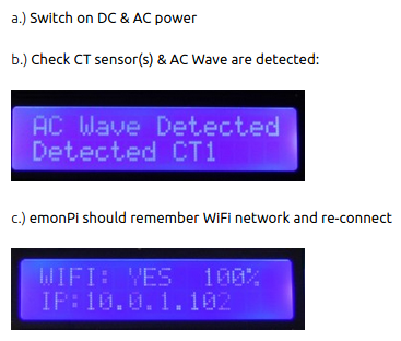
So on a practical note, when you followed the online instructions to first set up your OEM hardware, did you plug in a monitor screen to your Raspberry-Pi via the HDMI port?
After all, you’ve bought the option without the integral LCD in the expensive aluminium case, so you can’t see these messages:
Do I assume you’ve bought the metal-encapsulated temperature sensors from the OEM shop?

This contains a Dallas DS18B20 chip, manufactured by Maxim, which sends data down a single wire (called a ‘1-wire bus’). So if the metal cylinder or the length of wire is constraining you, then you can pick up the 3-pin chip itself from loads of other suppliers.
Aside:
The equipment and strategies we’re describing here would produce some excellent projects of direct relevance to the fight against Global Warming and the company’s push towards Net Zero.
… So on a practical note, when you followed the online instructions to first set up your OEM hardware, did you plug in a monitor screen to your Raspberry-Pi via the HDMI port?
I did. I also downloaded the pre-built image and ran the Emonpi software on the old Pi-3 for a day or two before any hardware arrived, sitting in comfort at a desk with keyboard, screen and mouse. It made me rather unsure of how to configure things, but it works, and I haven’t got around to naming the feeds properly. With hindsight, I’d have been better to start afresh with a completely unconfigured system as soon as the hardware arrived.
Do I assume you’ve bought the metal-encapsulated temperature sensors from the OEM shop?
This contains a Dallas DS18B20 chip, manufactured by Maxim, which sends data down a single wire (called a ‘1-wire bus’). So if the metal cylinder or the length of wire is constraining you, then you can pick up the 3-pin chip itself from loads of other suppliers.
I did buy one, yes, but I haven’t plugged that in yet, having little interest, at the moment, in temperature where the meters are.
I want to monitor 3 temperatures at once (e.g. flow and return in one place, another temperature somewhere else), and plan to use my existing 3 thermistors and more Raspberry Pi/Picos … (I’ve made up some nice long leads too...
We seem to have very complementary skills ![]()
Indeed we do - ideal for collaboration …
(but not till after a trip to the pub...)
For the sake of others reading this in later weeks/months, I’m also posting questions about the emonPi Energy Monitor over on the Open Energy Monitor site. If it’s related to the hardware build, internal software, configuration or errors, then I’ll be discussing those details with the experts from the existing user-base.
That seems to be the best approach, allowing us here to concentrate more on the use of the equipment and the data it delivers to us.
Aside:
The equipment and strategies we’re describing here would produce some excellent projects of direct relevance to the fight against Global Warming and the company’s push towards Net Zero.
A great little aside this one,
OVO Foundation's mission is to give kids and young people all over the world a greener, fairer future. OVO staff have previously supported a few electronics/ programming initiatives (including CoderDojo) but the most relevant of the programmes supported by the Foundation is probably Climate Changers, and specifically the work they're doing with Energy Sparks. They teach school students how they can help to make their schools more energy efficient. And once they’ve got this new, energy-saving know-how, they can pass it on to their friends and families too. Part of their activities includes setting up clubs, so the equipment may be of interest to them. If not, OVO Foundation has lots of connections to school groups who have coding/ electronic clubs if that's of interest.
Keen to share your expertise and get involved in any way?
I think the Climate Changers organisers/mentors should be invited to the Forum.
If they’ve got secondary school students in their group (like an out-of-school club) then we could provide direction and encouragement for them to build a portable home-energy monitor, using the major parts available from the Open Energy Monitor shop.
The design of this is inherently safe. Current readings are taken using clamps, without interrupting the mains power. The voltage is obtained by inserting a 9vAC transformer-plug into a socket.

Once a school had such a piece of monitoring equipment, it could be loaned out to pupil’s homes for a couple of days at a time whilst it collected the data on an SD card.
So this would yield direct, tangible evidence on electricity usage for each pupil taking part.
They key bits where we could help are:
This would very much simplify the highly-technical discussions over on the Open Energy Monitor Forums and enable such a project to be more confidently taken on by teacher/parent organisers.
Erm…
If not, then I guess this current topic is heading in the right direction for you!
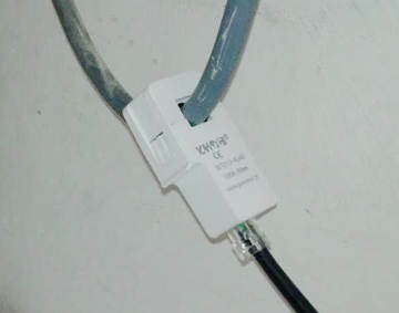
The design of this is inherently safe. Current readings are taken using clamps, without interrupting the mains power.
Not that I’m paranoid or anything, but the current transformer is something that, in the OEM system, can be unplugged from whatever is reading it. Of course I was careful to follow their instructions, which are very emphatic about making sure the current transformer remains plugged in when clamping/unclamping it around the supply cable. Otherwise there is a risk of generating a high voltage at the unplugged connector. I read that it has a zener diode to keep this high voltage at a safe level, but I wasn’t inclined to test this feature.
Would it make sense, in a school project, to adapt this detail so the current clamp remained connected (“plugged in”) all the time?
PS, if my understanding is correct, a “current” transformer like this steps the mains supply current down to the level of mA, and so must involve a turns ratio which is in the 1000s. Given the chance (i.e. with the secondary circuit open) the same transformer would step the voltage up by the same factor from a starting voltage which is the mains supply voltage...
As the emonPi is Open Source we can check the design to satisfy ourselves on the matter of safety.
The current-clamp inputs are on the emonPi shield for which the circuit diagram is available on GitHub.
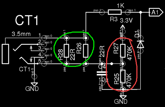
Here’s the input stage from a current-clamp jack socket to which I’ve added an arrow pointing to the zener diode:
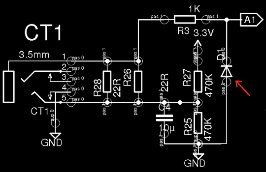
The zener will conduct if the voltage at that point exceeds 3.3v
The current clamps used by the emonPi will pass 50mA along the connecting wire for 100A peak mains current. That’s pretty small!
If the wire wasn’t connected to the emonPi board when the current clamp was placed around the mains cable, there is a small risk of damage to the circuit components when it’s plugged in because the voltage may be substantially greater than 3.3v. But I don’t see how there could be any risk to a human. The current simply isn’t high enough to pass through the skin.
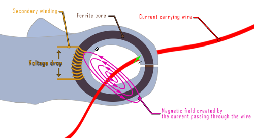
Nor do I see how a current transformer could operate ‘in reverse’ and yield voltages higher than the circuit being sampled. The clamp itself surrounds the cable being tested. This forms an embedded transformer, and the output along the clamp’s wire to the emonPi board comes from the thousands of turns on the secondary.
Current transformer theory is well expounded on the electronoobs site where they also show how to make your own!
Do you see things differently
Am I missing a possible safety issue?
Exactly the same clamp is used on my PowerVault Storage Battery which passes all necessary safety checks.
“Current” transformers are transformers which are (approximately) treated as sources of constant current (and the secondary winding is closed to make a circuit so that this current has somewhere to flow).
>Voltage] transformers (with the secondary winding attached to a relatively high resistance, including the possibility of open circuit i.e. infinite resistance) are (approximately) treated as sources of constant voltage.
The ferrite confines the flux (specifically, the flux that links the secondary winding) effectively enough that the same flux links the primary “winding” (I put it in quotes only because it really is a circuit that is closed by the other cable connecting supply and household), and it is fair to use the turns ratio to relate the currents.
From those figures, 100A and 50mA, the turns ratio must be 2000:1
A transformer is a transformer. That’s physics which I understand. This isn’t a matter of the current transformer acting “in reverse”: it’s the same action. Provided the flux linking the primary is the same as the flux linking the secondary, i.e. provided the ferrite does its job, the products of current and voltage in primary and in secondary windings are the same. (This is the point at which it becomes apparent that the ferrite can’t induce the implied current when the voltage gets very large. But, in the absence of the zener diode, it’s not at all obvious to me how large that voltage could get...)
If the secondary winding circuit is left open, then that’s the ratio by which the voltage across the primary winding will be stepped up. That’s what I was trying to say.
I don’t seriously think there is a safety issue (such things couldn’t be sold otherwise).
I’m not sure - do I see things differently to you?
Perhaps it’s just that I’m taking too seriously what would happen if the zener diode weren’t there. Although I would maintain that
“The current simply isn’t high enough to pass through the skin.”
Might indicate a misunderstanding - it is voltage that determines what passes through skin. As you say, there are momentary voltages that are higher than 3.3V. It’s that momentary voltage that determines whether a current will flow. I repeat, I don’t think these things are unsafe.
PS Perhaps it helps to think about the case (without the zener diode) where the secondary winding is closed with a known resistance and that resistance is varied between zero and infinite. (Left as an exercise for the interested reader...)
do I see things differently to you?
Well I hope so. Otherwise our collaboration on this project isn’t going to very fruitful! ![]()
As I see it, there’s only a certain amount of flux to go round.
If the open-circuit voltage rises towards infinity, the current decreases towards zero. I don’t think anyone’s yet been injured by zero current. ![]()
The same is not true of the analogue input to the Atmel chip on the emonPi board. Until that protection zener is fully conducting, there remains the risk of a high voltage frying the silicon gate.
Sorry, I was still editing my post while you replied. To boil it down. If the zener diode were removed, how large do you think that voltage could get?
10V? 100V? more? If not more, why not?
I’ve just checked the specification for the SCT-013 current-clamp on the YHDC datasheet. We have no need to be concerned. It includes a pair of back-to-back diodes to limit the voltage rise! ![]()
So there’s a belt and braces approach to limiting that voltage. Good.
You agree, though, do you, that there isn’t a principle that says, as that voltage rises, the current goes down?
Because that’s not how induction works.
As you said, Modbus (classic) is based on the RS-485 physical layer, which was both well documented and quite common. Annoyingly, it is just a bit different from a RS-232 serial connection, but that is to be expected with a 2 wire design. All these field buses are driven by cost and simplicity, so a lot of them use just 2 wires.
But it is very much a legacy standard at this point, and prices for the interfaces have gone up a bit. You can get a number of hats, and you can get USB adapters with corresponding software. I would do that just get a work endpoint, unless you already have one.
You should also be able to buy a used PLC for little money. Or just an endpoint? It is a bit of a different world, but it has its own kind of logic.
I realise that current doesn’t fall proportionally to the rise in voltage in a standard power transformer. But I believe a current transformer has a characteristic in which this suggestion isn’t too far removed from the truth!
The SCT-013 is designed to connect across a fixed resistor {*}
The cross-section of the ferrite ‘ring’ is massively greater than the cross-sectional area of the wire in the secondary coil. The flux is very low.
As the voltage induced across the secondary increases, you rapidly reach the point where the secondary is saturated.
If you replace the resistor in the emonPi with a higher resistance equivalent to human skin, the current remains fixed in proportion to the primary current, so the voltage rises across the secondary. It simply saturates quicker.
At saturation point no further energy can be passed to the secondary.
{*} The emonPi design uses two resistors with the input being applied to their mid-point. This allows current to be measured in either direction.
Thanks very much for this explanation,
I realise that current doesn’t fall proportionally to the rise in voltage in a standard power transformer. But I believe a current transformer has a characteristic in which this suggestion isn’t too far removed from the truth!
The SCT-013 is designed to connect across a fixed resistor {*}
The cross-section of the ferrite ‘ring’ is massively greater than the cross-sectional area of the wire in the secondary coil. The flux is very low.
As the voltage induced across the secondary increases, you rapidly reach the point where the secondary is saturated.
If you replace the resistor in the emonPi with a higher resistance equivalent to human skin, the current remains fixed in proportion to the primary current, so the voltage rises across the secondary. It simply saturates quicker.
At saturation point no further energy can be passed to the secondary.
{*} The emonPi design uses two resistors with the input being applied to their mid-point. This allows current to be measured in either direction.
I just need to remind myself a bit more about how B and H arrange themselves in response to electric currents in the presence of materials like ferrite, i.e. how ferrite materials do their job.
At this point, the way I see it, there is a certain amount of flux around the primary. Magnetic flux is determined by the current and, as you put it so concisely, there’s only so much flux to go round (pun intended, I’m sure). The ferrite works, I expect, essentially by concentrating that flux into the volume it occupies (and it really only achieves that just as the ring is closing - until that moment, the gap in the nearly closed ring means that a significant amount of flux does not link the secondary winding). (At this point, I’m vaguely tempted to see if there is an easily accessible point in the Emonpi to which I can hook up my oscilloscope in the hope of observing that induced current appear just as the clamp is being closed. If not, I’ll have to rig up something separately.)
hBut … hang on … if the protection is in the input stage, inside the Emonpi, how do things work (and how does that help) when the current transformer is clamped onto the supply cable if it’s not connected to the Emonpi? How do the zener diode and back-to-back diodes help if they’re elsewhere?
Edit - the zener diode in the Emonpi can’t help, but the back-to-back (zener!) diodes are in the clamp itself, which is where something is needed!
(I need to read more carefully the first time...)
It was the possibility of significant voltages being present on the connector, dangling there, unconnected to the Emonpi that I was originally asking about. I seem to be back where I started. If I do rig up something separately, I suspect I do actually need to be careful.
Resuming ...]
So, once everything is in place: clamp is closed, the ferrite is essentially continuous, the secondary winding is short circuited by a zero resistance conductor, I can try to answer my own question. Which is, what happens as the resistance of that short-circuiting conductor is increased from zero?
My (admittedly simple-minded) reasoning was that, other things being equal, the current remains the same and, as that resistance is increased, the voltage grows with it. What I will try to work out for myself next is, how best to understand the relevant ways in which “other things being equal” fails to be a useful starting point.
Thanks again :-)
I’ve just checked the specification for the SCT-013 current-clamp on the YHDC datasheet. We have no need to be concerned. It includes a pair of back-to-back diodes to limit the voltage rise! ![]()
I assume you intended to link to this,
Just to wrap up this little exchange, I offer the link to OEM’s very own independent test report on the current clamp (by the ever-helpful Robert Wall) which says
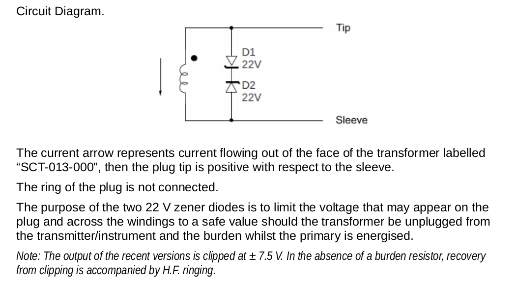
The main text refers to tests on an earlier model, the text in italics refers to the item currently available.
In light of that, and to continue from my previous comment/question:
So, once everything is in place: clamp is closed, the ferrite is essentially continuous, the secondary winding is short circuited by a zero resistance conductor, I can try to answer my own question. Which is, what happens as the resistance of that short-circuiting conductor is increased from zero?
My (admittedly simple-minded) reasoning was that, other things being equal, the current remains the same and, as that resistance is increased, the voltage grows with it. What I will try to work out for myself next is, how best to understand the relevant ways in which “other things being equal” fails to be a useful starting point.
The answer must be that, for example, if the mains supply current in the primary winding is at the limit, 100A, then the current transformer output rises from zero to 50mA as the clamp is closed. If we then start to increase the resistance through which that current is flowing, the current remains unchanged, and the voltage across that resistance grows, until it gets to around ± 7.5 V, which is when the back-to-back zener diodes do their thing. At this point, the variable resistance will have got up to ~150 ohms, I suppose? As the resistance is increased beyond ~150 ohms, the voltage across it remains at ± 7.5 V so the current flowing through it must fall in accordance with Ohm’s law. I can cope with electronics at the level of what would once have been A-level physics :-)
As you will see, I have to explain things to myself in very elementary terms, but hope that I might still have something to contribute to collaboration…
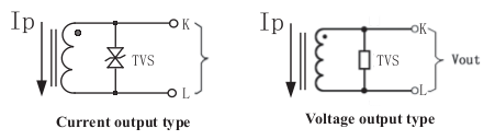
PS - why did OEM opt for the current output version of the clamp? I assume this was because they can gain better control over the accuracy of the current measurement. By connecting the output to their own load, consisting of possibly higher precision/stability resistors than are hidden inside the clamp, they can estimate (and improve) the uncertainty on the Emonpi’s measurement of supplied current (and ultimately supplied power).
why did OEM opt for the current output version of the clamp?
I believe that sensors based on current are favoured because they are more tolerant of long cables, poor connections and hostile environmental conditions:

The SCT-013 current clamp is feeding a 470kΩ resistor in the emonPi monitor.
So if I use a kinked connecting wire running from my garden shed the entire length of the garden, through puddles, and with breaks mended by twisting the internal wires together, I might add 200Ω resistance to the path. I’ll still be better than 99% accurate on the current measurement ![]()
Remarkable. If I understand correctly what you mean by “feeding”, did I make a mistake in the comments about 150 ohms? Wouldn’t a 470k load put the zener diodes well into their limiting region? why would the signal from the current clamp relate to the mains current at all?
I understood the point of current mode to be that the load should be well below that point p150 ohms], so that the current is indeed hardly influenced by lead resistance (although, obviously, 200 ohms would not be low enough for that to be true).
Perhaps that 470k is in parallel with something much smaller, so that the combined resistance is a lot less than 150 ohms. (Still important that both be precision resistances tho...)
Agh - mea culpa!
I woz reading the schematic incorrectly.
I looked at the potential-divider setting the mid-rail voltage of 1.15v when I should’ve been paying attention to the pair of 22R resistors in parallel.
That was a waste of time creating my earlier pretty graphic.
I’ll go back to building my oak porch for the rest of the day 
I’ll go back to building my oak porch for the rest of the day
I suspect you’ll have as much fun with that as I’m having implementing a demonstration of how to solve that old “missing data” problem...
Take care, BW
(I did get as far as looking at that diagram after my comment, but really really am not proficient enough at deciphering such things to have spotted that those resistors were connected in the way I was thinking of ...)
No account yet? Create an account
Enter your E-mail address. We'll send you an e-mail with instructions to reset your password.