Tutorial

An electric vehicle (EV) charging point installed at home

An electric vehicle (EV) charging point installed at home
Userlevel 7
Badge +2

Updated on 11/12/23 by Emmanuelle_OVO:

Please be advised you must employ a qualified electrician to undertake the work outlined in this user-created guide. Given the cost/time requirements as well as the loss of smart charging benefits, OVO Energy would recommend a smart EV charger instead of a self-installed charger described below.

Want to find out more about OVO’s EV plan? Check out this topic: 


.


As a new owner of an electric vehicle (VW ID3) I am well aware of the plethora of companies who wish to sell me a charger, such as OVO here. Each of them is apparently better than the previous one and comes with an array of bells and whistles . Most chargers are bundled into a package deal offering me cheaper rates and access to a thousand or more charging points across the country.


So I need a home charger too, right?


Wrong.  Despite its name, the ‘charger’ really only performs two functions:


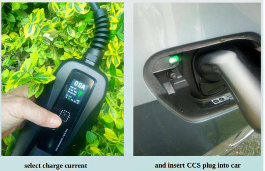
  • It can reduce the current available to the EV if required
  • It allows the configuration of charge time and duration


The actual charging electronics is built into the car… not the charger! Most EVs also allow the user to set up charging times, either using an internal touch screen, voice control or an App on your SmartPhone.


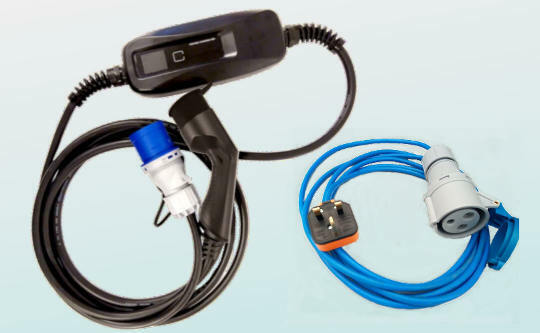
So until I know what sort of charger I want, all I actually require is an external socket capable of delivering the equivalent current to my car. Most home chargers are rated 7.5kW, which means they take 32 Amps.


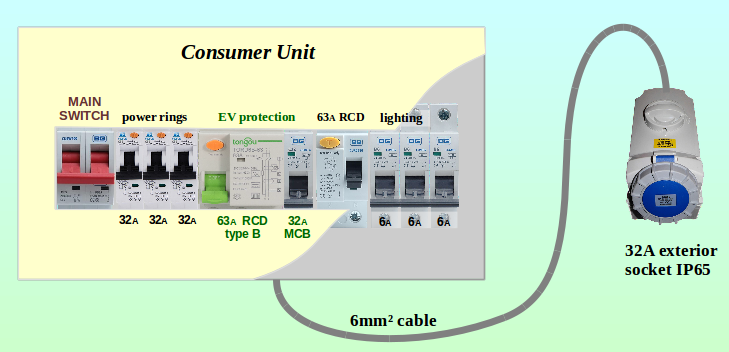
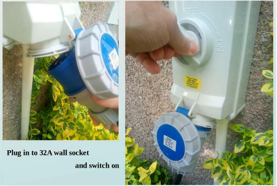
Here is a switched 32A external socket. Initially a lead can be plugged in, and it can be changed to have a charger connected at a later date.


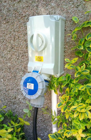
External sockets are marked with a code that defines how well sealed they are against water and dust. The socket above is rated IP67, which is as high as you’re ever likely to find. With the cap covering the downwards facing terminals, it can withstand a full-on attack with a pressure washer!


Even when a connecting cable is plugged in, the socket’s contacts still cannot be reached by the highest level of hurricane you’re likely to face without the house falling down anyway.


What are the benefits of using an external 32A (7.5kW) socket?


  1. Any qualified electrician can install it. They don’t need to be separately authorised to install charging equipment.
  2. A proportion of the installation work for a charging point is the running of the cable. The electrician will specify this. Its route may include moving furniture, lifting of carpets and floorboards. That really doesn’t warrant paying a charger-specialist to undertake.
  3. If your Consumer Unit needs extending/replacing to allow additional space for the EV protection components, then a local electrician is ideally suited to undertake that work, most of which involves the existing house electrics.
  4. A local electrician is well placed to make the LCT Application to your Distribution Network Operator (DNO).  It requires undertaking a Load Survey of the house, excluding the LCT device(s) which the application is being made. The survey must find the peak-usage required by the house, possibly by having an energy monitor being left on site for a period.
    That peak demand is added to the rated specification of the EV charger (and any other LCT devices) to arrive at the Maximum Demand (MD) for the property.
  5. If you later decide on a charger, then the same cable can be used. The socket can be moved to allow a 2-way switch to be fitted. This can select between the EV charger and the 32A socket. Should the charger have a fault, you still have a wall socket from which to charge the car.

(Calculating the Max Demand for a house is described in the topic Energy demand, supply and flexibility)


So what do I need at the Consumer Unit end of the new cable run?


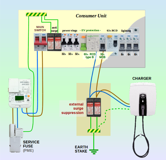
A suitably heavy-current cable connects the external socket back to the house Consumer Unit. If that cable is underground or clipped to the outside of the house, then it will usually be an armoured (SWA) construction.


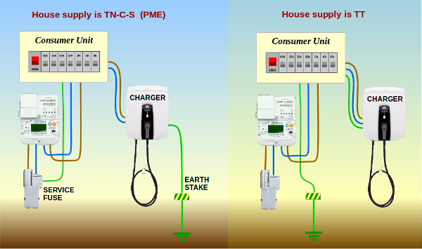
If you don’t understand this diagram, that’s because it’s intended to be shown to your electrician! Unqualified people are not permitted to work on mains electricity wiring in the UK, even if it’s your own house.

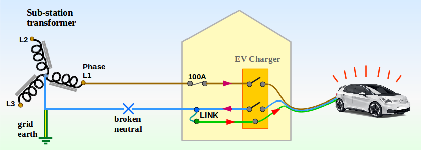
The method to provide the safety earth connection to an EV Charge Point is critical. The earthing rules must be adhered to whether you have a 32A charging socket like mine, or a full-blown EV Charger.

Earthing will differ according to the way in which the electricity feed is supplied to the house from the Distribution Grid.

The two most common methods are TN-C-S and TT which are shown below, but there are other arrangements. A qualified electrician will identify the type of supply and will test the earthing as part of the installation work.

different electricity supply methods

The reasoning behind the way in which the earth connection is provided is explored in greater detail later in this topic.


Your EV Charge Point requires an MCB (Miniature Circuit Breaker) rated at 32Amps to protect the cable between the Consumer Unit and the exterior socket. The MCB is normally chosen with a C-curve. This defines the trip-time when there is a fault.

Most household MCBs are chosen to have a B-curve. The C-curve is more tolerant of high-current surges at switch on/off. That’s what we usually need for charging our EV. We don’t want the MCB tripping every time the charge-cycle starts!

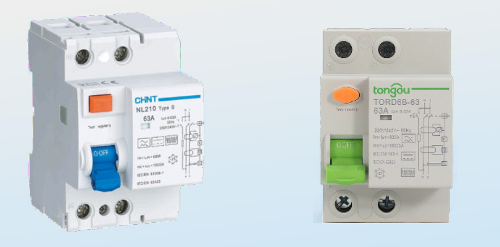
Supplying the power to that 32A MCB is a Residual Current Device (RCD). This provides operator safety and protection. An RCD measures the difference between the current on the live wire and the neutral/return. If they aren’t in balance then there must be a fault and the trip opens the contacts.


Type-B RCDs from two different manufacturers

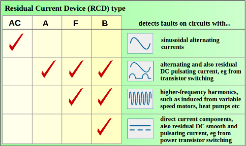
However, some electrical devices distort the 50Hz sine-wave used for UK mains power.

EV chargers fall into this category. They can induce higher-frequency ‘harmonics’, or shift the sine wave by adding in an element of DC (Direct Current). This can prevent the RCD from tripping out when it should, or needlessly tripping when there isn’t actually anything wrong.

Experience with this phenomenon was gained by OVO during the two years of their V2G charger Trial. It resulted in sites being fitted with Type-B RCDs which are specifically designed to cater for these anomalies.


categories of RCD

Type-B RCDs should not be confused with an MCB over-current device having a B-curve timing characteristic. These are two quite separate concepts.

An RCB with Type-B sensing is expensive… at least £200 at the time of writing. So if you’re paying less than that, then you’re probably not being offered what you need!


Consumer unit, lower half with EV connection box below it

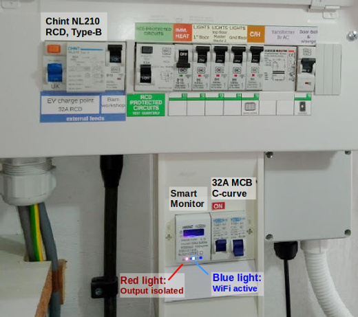
In the above photo there wasn’t enough space in the main Consumer Unit to fit an additional Smart Monitor module. This was therefore placed in a separate enclosure below, with the 32A MCB alongside it.

The Smart Monitor isn’t essential. It uses a WiFi connection to a SmartPhone App which displays the power used. The App also allows the external socket to be isolated, thereby preventing anyone else from using it.


How well does it work?

Let’s remember that this is an interim measure for me. Although I can preset charging-times using the car’s electronics, there are other automated features I’d like once I’m confident that a particular model of Smart Charger offers them.

My house already has the benefit of PV Solar Panels (5.1kW grid-connected) and a small Storage Battery (8kWh). I can use both of these to help maximise the quantity of free solar energy used to charge the car.


electricity consumption using PowerVault battery storage software

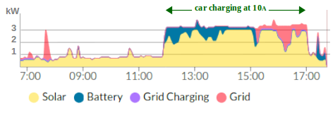
The above graph is from early June. It shows a household base-load of 0.8kW, almost all of which is being satisfied by solar power before 7am. At noon the PowerVault battery was over 50% full and there’s at least 2kW of solar available. That’s the point when I could start charging the car at 10Amps.

A higher charge rate than this would be needlessly taking electricity from the grid. But until 15:20 there’s enough energy from solar (yellow) plus what was already in the PowerVault battery (blue) to fulfil the 10A charge-rate I’d set. The Battery was then depleted, and any further deficit was taken from the grid (red) to keep the car charge at 10A.

By 17:10 the sun was no longer shining directly on the PV Panels, so I stopped charging the car. That low-current charge had added 12½kWh to its battery. Any surplus solar after then was used to restore energy back into the PowerVault battery.

Yes, it’s a very manual system, but if I keep watch on my solar generation and the weather forecast, then it serves well.


Hope this helps!


18 replies

Userlevel 7

Thanks for posting this, @Transparent - could we see the VW ID3 charging in action? 

Userlevel 7
Badge +2

I’ll resist the temptation to post a 6-hour video of the ID3 charging in action… :hugging:

But let me first show the two cables I use:

CCS Type-2 charging cable set

The thick black cable came from EV One Stop on overnight delivery at £250. It has the 32A “commando” plug at one end and the CCS type-2 connector for the car at the other. The hefty looking box has only one function - to allow the current to be preset between 6-32A.

I could have purchased the same black cable directly from a Chinese supplier at £150, but with a shipping time of 10-days.

The thinner blue cable has a 32A socket at one end, and a standard 13A plug at the other.

At my own house I can use just the black cable. If I’m at anyone else’s house, then the blue cable can be added on to allow a maximum 13A to be taken from a standard house socket.


Starting the charge is very straightforward:


By default a Volkswagen ID3 will automatically start charging until it reaches 80% capacity. So unless I want something different, such as delaying the start time, I don’t have to configure anything on the internal controls.

Whilst charging is in progress a green light slowly pulses next to the CCS socket on the car, and the lead cannot be removed.

When charging is completed, the green indicator turns white. The CCS plug can still only be removed if it is ‘unlocked’ using the key fob. This allows charging in a public location without anyone being able to steal the cable.

Userlevel 6
Badge


The thick black cable came from EV One Stop on overnight delivery at £250. It has the 32A “commando” plug at one end and the CCS type-2 connector for the car at the other. The hefty looking box has only one function - to allow the current to be preset between 6-32A.

Yes, this is a very flexible solution. IEC 60309 is quite common, so you can also use it out and about. If you want to be regulation compliant, you also need a local earth spike, (or the EVSE needs to have a ground fault protection device). 


Userlevel 7
Badge +2

Great to have corroboration from @MrPuds  :slight_smile:

The circular blue plug and socket I’ve used to are the IEC60309 items he refers to. The term ‘Commando’ plug is actually the name given to this series of connectors by MK, but has entered common usage. It’s akin to calling all vacuum cleaners a ‘hoover’.

EVSE is Electric Vehicle Supply Equipment.

My house has a TT supply, which means that I already have an earth stake. I’ll try to put together a diagram to show why @MrPuds has raised this issue. It is important because there can be fault conditions whereby the metalwork of the car becomes ‘live’.

Userlevel 6
Badge

My house has a TT supply, which means that I already have an earth stake. 

I think that is worth mentioning, because TT is quite rare in the UK. And in this application (not just in this application), it has clear advantages. It should be standard, but hey, if you can save 50 quid building a house, the developer will do exactly that. 

Userlevel 7
Badge +2

NB This section shows a wiring method for an EV Charge Point which is wrong. It demonstrates how incorrect earthing can give an electric shock when the car is touched.

Here’s the diagram I referred to above. It shows a possible fault on a house connected to the substation by the TN-C-S (PME) system, which is the dominant configuration in urban areas of the UK.

for clarity only the secondary coils of the transformer are shown

The neutral wire is also used to create the earth for the house. This connects back to the central tap of the wye-configuration windings at the transformer.

Under normal circumstances the current flows through the live (phase) wire to the EV charger (the ‘load’), and returns via the neutral.

However a break in the neutral feed to the house allows the voltage of the house ‘earth wire’ to rise (red arrows in diagram). Anyone touching the metalwork of the car will complete the circuit back to the transformer via the ground, thereby receiving an electric shock.  :zap:

Such a neutral fault is not as uncommon as you might suppose. There are about 250 - 400 instances recorded in the UK each year, of which 10% cause injury.

To avoid this possibility, electricians installing EV chargers on a TN-C-S site most often install a separate earth for the charger by using a ground stake. There are other solutions built into some chargers and the manufacturer’s instructions will make this clear.


It is also mandatory to install a Type-B residual current circuit breaker (RCD or RCCD), whether the mains supply is TN-C-S or not.

These two safety requirements form part of the IET Wiring Regulations; Amendment 1 (2020), a read-only copy of which can be downloaded here.

For a correct wiring diagram see below.

Userlevel 7

Great guide as ever, @Transparent  - particularly interesting to see how you’re making use of that solar energy and stored battery energy - what a green machine!


Wonder how long it’ll be before we see public solar-powered EV charging stations like these replacing the petrol stations of today...

Userlevel 7
Badge +1

Well, as it just so happens some public EV Chargers are already solar powered. :wink:

In some countries, solar panels and wind turbines are actually directly hooked up to the chargers as the primary power source - there’s even a few that have solar panels covering the entire roof of the charging station. If memory serves, a few Tesla Superchargers in the USA are set up this way for example.

Given how powerful Tesla Superchargers are, pretty much all of them around the world also utilise battery storage capability to help reduce, manage and balance out the load on the local grid. The batteries at the Supercharger get juice via the usual methods such as from the local grid, solar power and wind power where available, and then these batteries are used like a proxy to charge up any Tesla that stops by for a top-up. Pretty clever really.

Userlevel 7
Badge +2

Erm… almost all UK fuel-stations have (3-phase) solar panel installations on the forecourt roof, and have done so for the past quarter-century!

Around the Millennium, most PV Solar Panels being offered for sale were supplied by the likes of BP and Shell! That’s how petrochemical companies avoided getting slated at the millennium conferences… except for Exxon/Esso who failed to buy themselves a PV production facility in time. :open_mouth:

We discussed EV chargers with battery stores here 6 months ago. And I gave some real figures on the power-requirements for Tesla’s fast chargers too!

Due to late applications for network reinforcement of the Distribution Grid, many road-side service stations are installing on-site diesel generators to operate all the EV Fast Chargers they want.

How green is that? :face_palm_tone1:

Userlevel 7
Badge +2

@TransparentWelcome to the ranks of EV drivers !

Userlevel 7
Badge +2

I’ve had a few software failures in my new EV over the last month:


The VW package includes a call-out to a recovery service. But by the time they saw the vehicle it had sorted itself out.

Nevertheless, the engineer did say what they do under these circumstances. The ‘solution’ is to open the bonnet and temporarily disconnect the -ve terminal from the 12v battery which handles all the instrumentation.

Well if the approach is that simple, frankly I can do it myself.

I’ve added the appropriate tool to the glovebox

10mm insulated nut-spinner


Userlevel 7
Badge +2

Exactly the same issues with the Leaf (although I haven’t experienced any) usually when the 12V battery is a bit low and particularly if it’s on its way out.

Userlevel 7
Badge +2

There’s not a lot us end-users can do about that is there @PeterR1947 ?!

The internal software decides when to replenish charge in the 12v battery and by how much. In my case it was reading 12.1v which is still roughly a quarter full.

Even so, I’m a little surprised that the available capacity wasn’t greater. The car’s main battery had been charged to 70% the previous day, and the loss of displayed data occurred 7 miles into a journey. That’s odd timing if it was invoked by a low-battery issue.

Userlevel 6
Badge +3

Welcome @Transparent to the EV club and congratulations for ID.3 - excellent choice!

It will take some time for the range anxiety to settle in. I am sure you’re loving the torque and speed away at the traffic lights :)


Userlevel 7

Not sure anyone else spotted it but VW had some prime advertising for their EVs during a certain match last night - a sign of EVs becoming more mainstream if ever I saw one!:soccer:

Userlevel 7
Badge +2

I saw the adverts for the ID4 featuring on the signage around the pitch.

I’m also aware that VW are developing their own V2G charger system, based on the notion that it will create another revenue stream for the company. :thinking:

They really don’t yet understand the V2G concept, do they?

It might work in Germany where there are a great many more homes supplied with 3-phase electricity.

But if they try to use their own centralised charger control system, then it will surely fail.

You can really only have one electricity control mechanism handling devices in a single home, especially if the supply and demand from the local substation is constrained by the DNO - as it will almost certainly be in the UK.

I need to go and talk to VW.

Userlevel 7
Badge +2

Here’s the working diagram showing how to connect an EV charging point at a house which has a PME (TN-C-S) feed from the local substation.

charger connection for PME site with Type-2 surge suppression

This is a fully-engineered system with a Type-B RCD and two pairs of fast-acting suppression to protect against surges and nearby lightning strikes.

Note there must not be an earth wire connecting the charger to the Consumer Unit at a TN-C-S (PME) site.

The charger itself requires an earth, and it must be provided with its own earth-stake (or earthing-grid). This same earth-stake is used by the second pair of surge suppressors. This prevents a lightning strike entering the house via the charger circuit.

The surge suppressors limit the voltage rise which can occur between phase to neutral, and PN to earth. Those shown in the diagram are from Phoenix Contact’s Valvetrab range.

Surge suppression isn’t mandatory. An installation without it will still pass the required electrical safety certification. It should be regarded in the same way as an insurance policy. The EV and charger will operate without surge protection, but can be seriously damaged if the house is affected by lightning.

Userlevel 7
Badge +2

.I agree with OVO’s aspirations to advise customers to have a full Smart charger installed rather than a 32A charge-point such as I’ve outlined above.

However it remains the case that the charger functionality I’m looking for is not yet available. In the meantime I have a system which works and has the protection devices and surge suppression which would be needed for a charger anyway.

Government policy is to require all home-based EV chargers to be ‘Smart’. This is being discussed further on the topic Smart Electric Vehicle Charging Legislation.

Reply