

Due to inept official planning and misguided political priorities there seems to be a consensus that power cuts are more likely than usual this coming winter. In fact. preparation for power cuts was a strong motivation to me for installing extra storage batteries to keep systems operating during outages.
However, I am looking for some help in how best to achieve this.
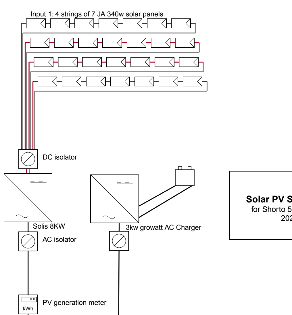
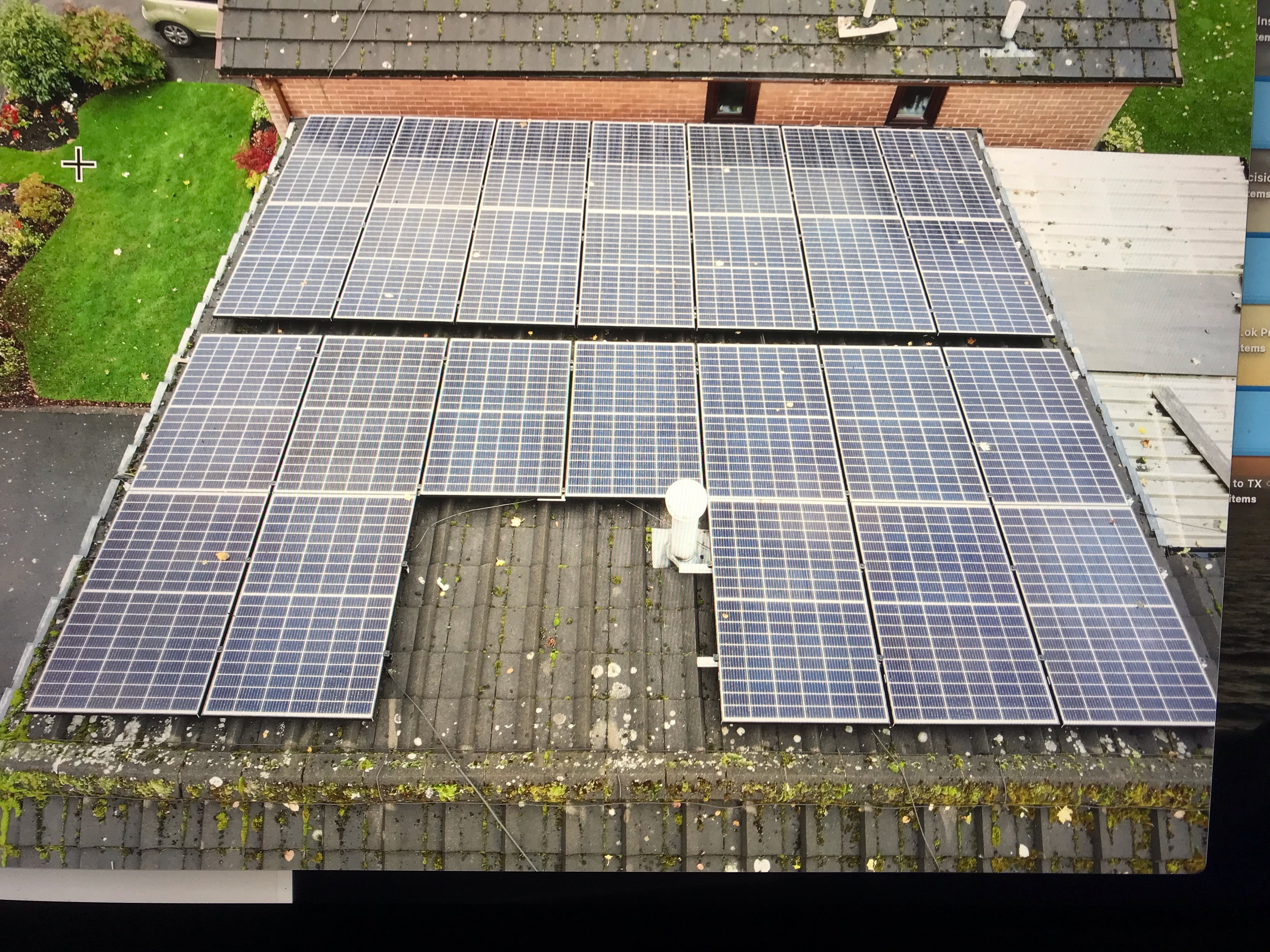
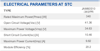
I live in Cheshire in the NW and have 28 JASolar PVMono 345 south-facing panels, nominal output 9.5kW.
4 Pylontech 3.5kWh batteries = nominally 14kWh capacity.
Pre-solar my domestic load averaged around 10 kWh per 24 hours and is still similar.
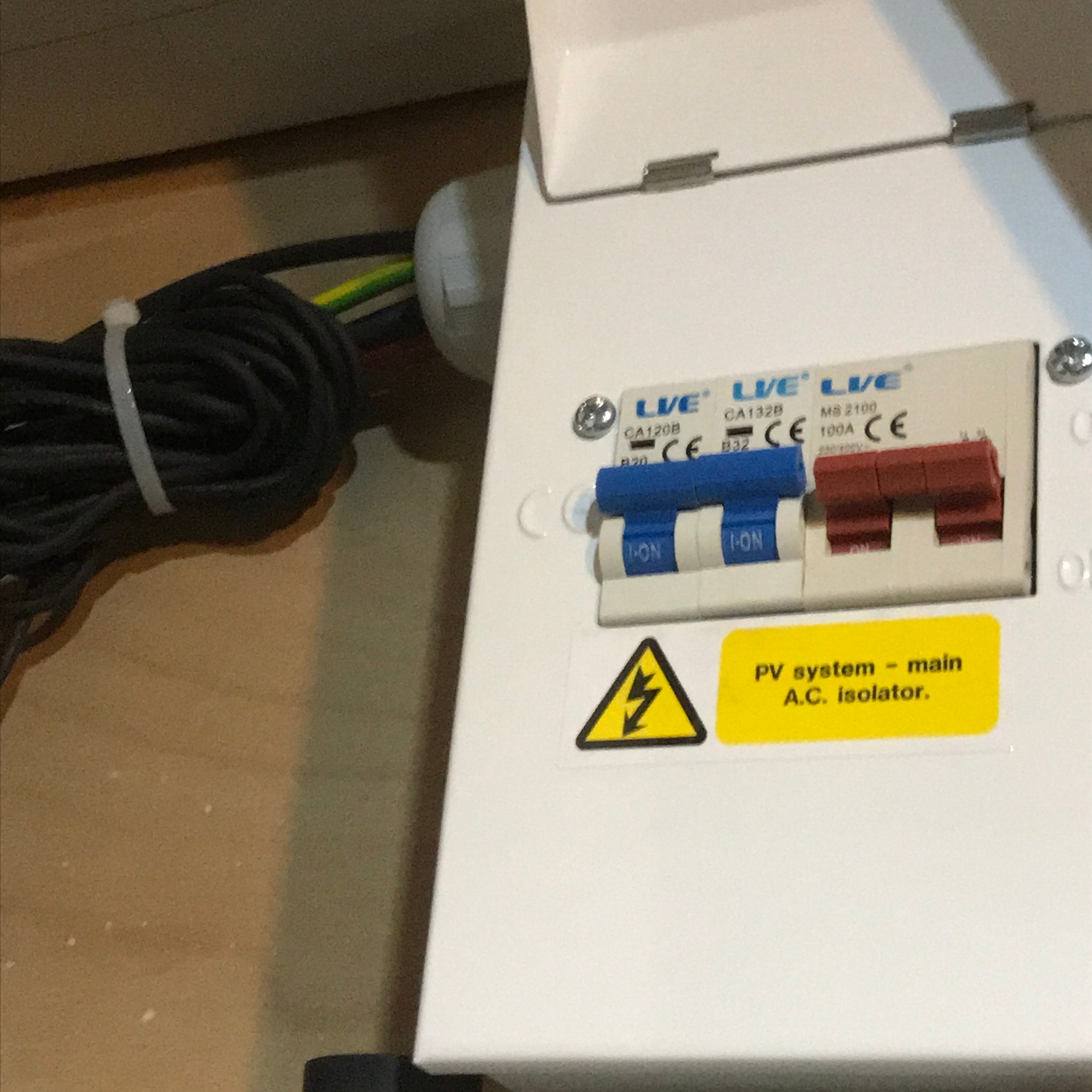
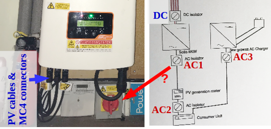
I don’t fully understand the relationship or the interface between the AC grid and my installation as it was all put in by a professional team.
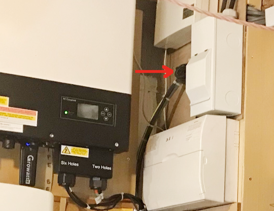
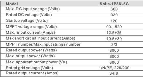
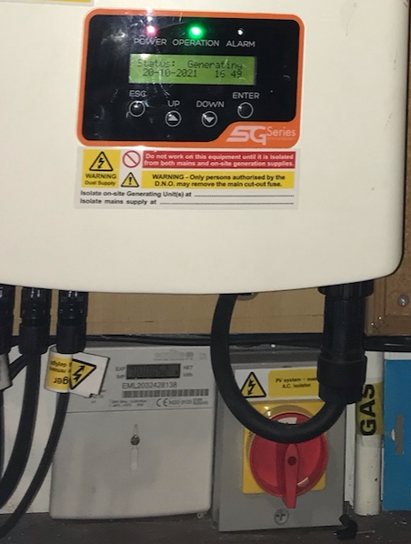
The main inverter is Solis 5G Single Phase.
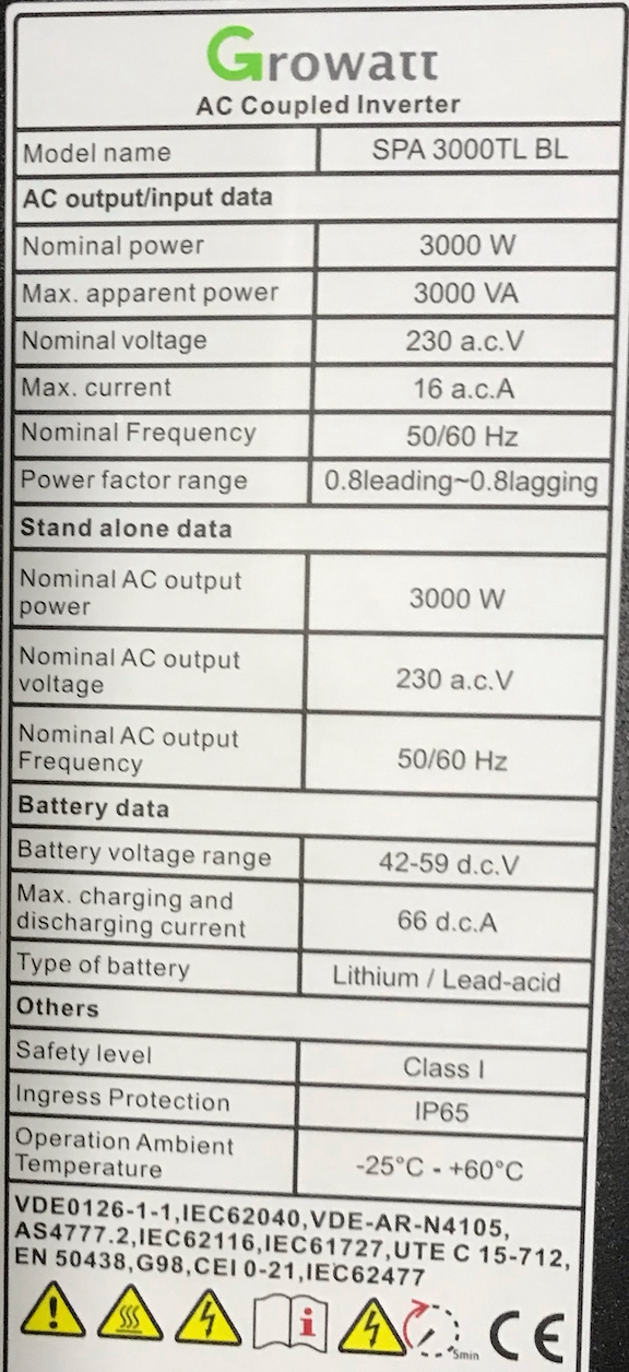
Batteries are controlled by Growatt SPA3000TL BL (AC Coupled inverter)
(BTW, does anyone really know what SPA means in this context? There are vague possibilities among the over 200 meanings listed in “thefreedictionary.com”: Switching Power Amplifier, or Serial Port Adaptor, or Solar Panel Assembly, and several more.)
On any reasonably bright day between April and September and especially with some sunshine my batteries become fully charged, the HW cistern is heated and the grid receives all my excess. The smart meter doesn’t move from one day to the next and I’m basically using solar for everything, which is gratifying.
As the community will be aware, October to March can be rather different. Much less solar input so that a lot of my power is drawn from the grid and the batteries are down to less than 10% capacity each morning.
They do sometimes fill right up after a few hours of winter sunshine, but are used up quickly once the day darkens.
I would like to explore 2 possibilities in preparation for if power cuts start happening:
- Some way to manually isolate the batteries once they are filled so as to preserve the stored energy to be available when the lights go out.
- When there is very little daylight and not much chance of charging the batteries from the panels, some way to manually charge them from the grid while it is live and then reconnect then during the next power cut.
Does anyone have experience of this, or do you think it could be done?
Thanks, David 101